

This was the first circuit board I have ever soldered, so I was pleased that the 555 timer kit that was included in the Kickstarter IR camera package had a handy illustration of what your soldered contacts should look like. It was disconcerting that most of my contacts closely resembled the image of how the contacts should NOT look, but my completed timer actually worked!
But maybe not really. Although the onboard LED blinks and the relay clicks in time with the intervals set by the potentiometers, I have not been able to get the timer to output a usable pulsed signal. Jeff was having problems as well, and he thinks it is a power issue – the device might need a stronger battery to operate correctly. I have been running it with the 12 volt A23 battery Jeff supplied, and I have not tried another 12 volt power source. The product description says “12VDC…15VDC / 100mA.” I think my two 6v lantern batteries would be too much (about 300mA apiece).
I have tried different batteries for the other part of the timer. The output circuit needs its own battery, and this would supply power to the cameras through the USB cables. Canon Powershots are supposed to need about 3.5 to 5.5 volts to be triggered through the USB ports, and it is possible to damage some cameras with more than 5 volts. I tried without success to power the output circuit with: 3x 1.5v button cells (=4.5v), 3x 1.2v rechargeable AAA (=3.6v), 4x 1.2v rechargeable AAA (=4.8v), 6x 1.2v rechargeable AA (=7.2v).
These tests were done with a test lamp, NOT a camera. So the timer was running (on a 12v A23 battery) and the output terminals were connected to a test lamp and battery. The failure always exhibits what might be a diagnostic feature (to someone who understands this stuff). When the power and test lamp are connected to the COM and NC terminals, the current is continuous even as the timer is going through its intervals. When the power is connected to the COM and NO terminals, there is never any current. So it appears that the relay is not doing its switching thing. The product description says “3A/24V output relay with dry switch-over contact.” So maybe it will work with closer to 24 volts on the output circuit. But that is way too much to run through a USB cable to the camera.
I have successfully triggered the Canon A495 from the IR camera pair with: 3x 1.5v button cells (=4.5v), 3x 1.2v rechargeable AAA (=3.6v), 4x 1.2v rechargeable AAA (=4.8v).
Jeff said he was triggering the camera with 6v. Don’t try this at home!
I think I am stumped. Any suggestions about what to try next?
17 Comments
Chris - if you're able to manually trigger your camera with the above voltages, you know I think you may be right and it's a faulty relay... can you upload a youtube clip or even an audio file of the "clicking" noise? It'd be surprising if you can audibly hear a sharp clicking but there's nothing happening. But the fact that you get a closed (on) connection for COM and NC but an open (off) connection for COM and NO suggests that the relay is the issue... worth trying out?
BTW:
COM = Common NC = Normally Closed ("on") NO = Normally Open ("off")
Took me a little while to "get" that but it was helpful to me.
Posting soon with my own issues :-(
Is this a question? Click here to post it to the Questions page.
Reply to this comment...
Log in to comment
Here are two pieces of evidence that are consistent with the failed relay hypothesis. 1) When I first got the timer working (with nothing connected to the output block) I noticed that the entire device moved every time the relay clicked. It just skittered a fraction of a mm at each interval. It does not do that anymore, and I cannot feel anything when I touch the relay as the timer is running, suggesting that the physical switch is not moving. I can still hear a clicking, but it is very faint (too faint for my recording equipment).
2) My first test of the output circuit was with two SD1000 cameras. I think both cameras triggered for the first few cycles of the timer. Then they never did again, so I started testing with a test lamp which produced the results above.
So the output circuit worked originally, and might have stopped working less than a minute into my first test. That could be because the power from the A23 battery dropped too low, or because the relay failed, or because some other component of the timer failed.
I can pick up another relay at Radio Shack for a few bucks (and get more soldering practice).
Good idea?
Is this a question? Click here to post it to the Questions page.
Reply to this comment...
Log in to comment
Ok, i was going to post a separate note, but since you say the "clicking" is almost inaudible, i think we are having the same issue - the relay is not being driven by the battery. What's odd is that my original device does work. Anyhow, here is the video:
Reply to this comment...
Log in to comment
The timer I have seems to be different from all three of yours. The relay NEVER makes a loud click (although it does make a barely audible click). The LED flashing responds well to adjustments of both potentiometers. I can duplicate the always-on LED by turning both pots all the way CC, but otherwise it flashes as it should.
So you have a different problem than I do.
Reply to this comment...
Log in to comment
I see, OK. Well i think that finding a more powerful 12v source (more current) is not a bad next step for both of us. I think it may be more likely to solve your issue though (gut feeling).
Reply to this comment...
Log in to comment
Excellent gut feeling, Jeff.
I powered the timer with 12 rechargeable 1.2v AA (=14.4v) and it worked fine.
It makes a lot of noise and the test lamp blinks on cue. The test lamp was powered by 3 rechargeable 1.2v AAA (=3.6v), and it also worked with three 1.5v button cells (=4.5v).
I also tested it with the visible/IR pair of A495 cameras, and either output battery source triggered both cameras in perfect synchrony. Either of these sources is also lightweight enough to fly, although the three button cells will have to be tested for endurance.
So now we need a 12-15 volt battery that is sufficiently lightweight to fly, sufficiently affordable, and will last for two hours.
Anybody know of such a thing?
Is this a question? Click here to post it to the Questions page.
Reply to this comment...
Log in to comment
Great! I should try the same thing.
So the 23A battery was my best attempt to find a lightweight and cheap 12v source. But it seems it is not enough. Would 2 or three of them in parallel help? Or we could start googling around for 3 or 6v batteries that don't weigh much.
Gah. If we could find a relay that doesn't require as much power, or switch to a transistor of some sort, this really shouldn't be a problem. This is an old circuit design, and was probably based on the idea that you'd be running it off some reasonably powerful source, not a tiny lithium battery. They were probably thinking about a model train set transformer.
Is this a question? Click here to post it to the Questions page.
Reply to this comment...
Log in to comment
The relay might be a bit of a battery drainer. Some options:
I think the 555 should be able to directly drive the canon USB trigger, so there may be a way to run the 555 on approx 5 volts, and bypass the relay altogether to greatly reduce the power draw. If you can post the schematic, I can try suggesting how to mod the circuit.
We use this low-power $15 intervalometer in our timelapse work: http://www.amazon.com/NEEWER%C2%AE-Timer-Remote-Control-RS-60E3/dp/B003Q9RERY/ref=sr_1_2?ie=UTF8&qid=1335997567&sr=8-2. It drives a Canon G11 camera directly, or you should be able to modify the cable and add a 5V source to trigger CHDK cameras over USB.
CR123A is a 3V primary cell with serious energy density (over 3 watt-hours in a very light package). You can stack a few of these to get the voltage you need, but they're very spendy.
Is this a question? Click here to post it to the Questions page.
Reply to this comment...
Log in to comment
I found a couple of 9v batteries lying around and neither of them would power the relay, but they did make the LED light on cue. I connected both batteries in series (18v) and the timer worked fine. Maybe one fresh 9v battery would work.
Reply to this comment...
Log in to comment
Thanks Randy. You must be right about the relay. Here is the circuit for the MK111 timer: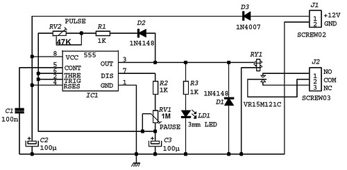
The assembly manual (pdf) has some more specs for the components as well as this schematic again. It would be great to trigger the camera without the relay.
I tested some more batteries. The timer runs (the LED flashes) but the relay does not switch with six or seven eneloop AAA (7.2v or 8.4v). It takes eight eneloop AAA (9.6v) to get the relay to operate. I am endurance testing right now (not me, the timer and two cameras).
The CR123A looks like a good solution. About $2 apiece, and four of them should do the job. Much heavier than I would like, especially since the camera might need separate power, but maybe the best we will do with the MK111.
Thanks for your help.
Reply to this comment...
Log in to comment
Here are four CR123 rechargeable batteries and a charger for $26: http://www.amazon.com/RCR123A-Li-ION-Rechargeable-Batteries-Charger/dp/B002UEE7SU/
These can have 4.2 volts apiece when freshly charged, so the MK111 might need only three of them.
Finding a holder for 3 or 4 of these might be a challenge.
Reply to this comment...
Log in to comment
Randy's response got lost (my bad?) so here is his latest comment:
Thanks Chris for the schematic. I've done a little poking around and here's what I've learned:
There are two different commonly used variants of the 555: LM555: Requires supply voltage between 4.5V to 15V. Can source up to 100mA from OUT (pin 3) TLC555: Requires supply voltage between 2V to 15V. Can source up to 10mA from OUT (pin 3) According to http://chdk.wikia.com/wiki/USB_Remote_Cable, you don't need much current at all to trigger the camera -- the IXUS 80 for example uses less than 1mA. So either variant of the 555 should have no trouble.
Here's an experiment you might consider trying:
1) Disconnect the relay coil by cutting a trace between pin 3 and the relay coil. (Or you can remove the relay altogether). 2) Power the board with 5 to 6V, instead of 12V. After the half-volt drop from D3, this will provide 4.5V to 5.5V to your 555, and then your 555 will provide the same 4.5V to 5.5V to your camera via the USB cable trigger. If you have the TLC555, you can probably get away with a lower-voltage battery, maybe down to 4.5V, yielding 4V to your TLC555 and your camera, since the TLC555 works down to 2V, and I imagine the camera will still trigger fine down to 4V. If you want to reduce battery voltages by half a volt on both sides (e.g. 4.5V-5.5V or 4V-5.5V), you could short across D3, but you'd have to promise to never plug in your battery backwards. (Diode D3's role is to keep your board from letting out the magic smoke if you hook your battery backwards by accident). 3) Now connect the USB cable going to your camera to OUT (pin 3) of the 555, and the board's ground. You might consider jumping these signals to J2 for ease of connection, in which case you might want to disconnect J2 from the relay, or just use the two signals that are open-circuited when the relay is off (should be COM and NO). Note that you don't need a second power supply -- the 555 is supplying the ~5V signal directly to the camera.
If I were designing this circuit from scratch, I'd probably add a 5V regulator between the battery and the 555, so that you could use any battery voltage 6V-12V and still be confident about getting a controlled voltage to your camera.
Randy
Is this a question? Click here to post it to the Questions page.
Reply to this comment...
Log in to comment
Randy has confirmed that a good experiment would be to:
1) Build the MK111 timer without the relay. 2) Solder a wire between pin 3 (OUT) on the 555 and COM on the J2 terminal block 3) Solder a wire between GND on the J1 block and NO on the J2 block
It should then be possible to power the whole thing with just one 5-6v battery pack, and that power will trigger the camera shutters via the USB cables.
Can you guess if I am going to try this?
Is this a question? Click here to post it to the Questions page.
Reply to this comment...
Log in to comment
Very eager to see the relay-less design! I am endurance-testing two 9v batteries in series, which is ~18v. It did not immediately burn out the 555 :-) and has been going for ~15 min now.
I'll prob. let it run for 45 mins and check the voltage afterwards too.
25 mins and counting... hooray!
Reply to this comment...
Log in to comment
I got a five pack of 4LR44 6v batteries for $4.74 incl shipping (the price has since dropped). I haven't tried them yet, but two of them fit in a AA holder (tight fit, but very convenient). Also, if the no-relay configuration works, one of them should power the whole deal.
Is this a question? Click here to post it to the Questions page.
Reply to this comment...
Log in to comment
I posted a new note describing the successful modification of the MK111 timer following Randy's instructions. This seems to be a very good solution.
I was prompted to do the modification by disappointing performance of the unmodified timer with two 4LR44 batteries.
Reply to this comment...
Log in to comment
I got 504 gateway errors while posting this both times.
I posted a new note describing the successful modification of the MK111 timer following Randy's instructions. This seems to be a very good solution.
I was prompted to do the modification by disappointing performance of the unmodified timer with two 4LR44 batteries.
Reply to this comment...
Log in to comment
Login to comment.