Here are some first passes at a Raspberry Pi shield design. I don't quite yet know what I'm doing, but here's the rough idea I'm aiming at. I'm not sure how sensible it is, so I'd love to get any feedback!
It'd be nice to have a device that: - controls a filter switcher motor for rapid switching between filters - has both VIS and IR light sensors, to calibrate camera readings - allows for several additional sensors to be designed and plugged in (temperature, humidity, soil moisture, etc) - operates on battery power
Here is a first pass at a Raspberry Pi shield design for controlling a filter switcher, providing webcam calibration using a light sensor, enabling rechargeable battery power via a LiPo battery, and providing ports for other add-on sensors -- temp, humidity, soil moisture, etc. I don't yet have much experience designing printed circuit boards, so I'd love to get any feedback -- both on the schematics, as well as the overall design concept.
It'd be nice to have a device that:
- controls a filter switcher motor for rapid switching between filters
- has both VIS and IR light sensors, to calibrate camera readings
- allows for several additional sensors to be designed and plugged in (temperature, humidity, soil moisture, etc)
- operates on battery power
Further: we'd like to be able to place some of the sensors (e.g. the light sensor) in arbitrary orientations -- we want it to be getting a good reading, and not be obscured by other structures in our device (or the device case).
I started thinking about how to make this work on a Raspberry Pi, and I realized that one approach to this problem had some possible overlaps with an Arduino-compatible platform I'd been working on with friends, recently. We've been trying to come up with a slightly re-designed Arduino-compatible board that has a "port" structure allowing for a (somewhat) "plug and play" sensor architecture. We'd already begun to design the boards and start in on the peripherals, so I figured I'd leverage some of that work, here. Still not sure if it's the right approach, but in the spirit of throwing crazy ideas together and seeing what sticks ...
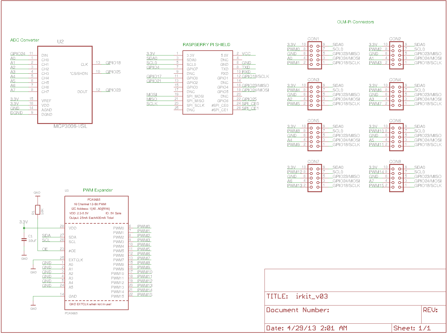
I designed a shield for the Raspberry Pi that simply adds a bunch of analog I/O (which the Raspberry Pi lacks, by default), and a bunch of additional digital pins (PWM-capable pins, to be exact -- I'm not sure this was wise, and I might need to switch this to a simple I/O expander). Here's the schematic for this shield, so far:
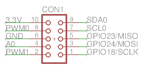
I also added eight "OLM-style connectors" (we've been calling the Arduino-compatible prototype I mentioned above the "Open Lab Monitor (OLM)" -- but we could henceforth refer to it as a "PL Connector", if folks like the interface!). Each of these eight connectors is a 2x5 arrangement of pins with connections to:
- 3.3 V
- ground
- SPI
- I2C
- two digital I/O pins
- one analog I/O pin
Which looks something like this:
I've been discussing this arrangement with friends, and I'm still not sure it's ideal, but what seems promising is that it'll allow for connecting to a wide array of off-the shelf sensors which use the SPI or I2C interface, as well as allow for folks to experiment with their own designs using standard digital and analog pins.
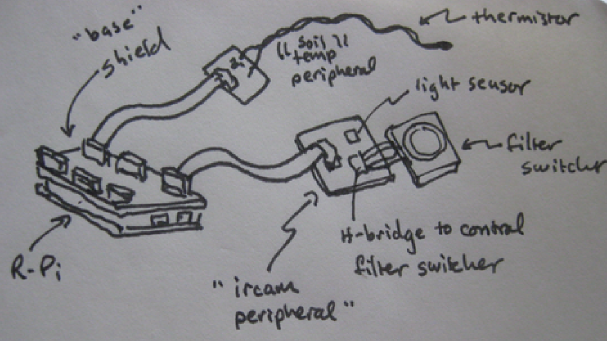
So, the idea is: we place this shield on the Raspberry Pi, and then we design one or several other peripherals that allow us to: control motors, sense light, sense temperature, what-have-you.
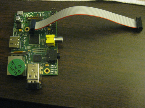
It seems to me that this could have several nice features: folks can choose from an array of sensor "plug-ins", or design their own; if there's a case for the main Raspberry Pi device, these sensors can be brought outside the box via cables. To wit: the 2x5 geometry has some nice, associated 6" ribbon cables associated with it on Sparkfun. Here's a photo of one of these cables (we ordered a few); in the photo, I'm holding an example of the sort of 2x5 "shroud" that they'd fit into (several of these shrouds would go on the shield, and one of them would be on each sensor / actuator 'peripheral' we'd design):
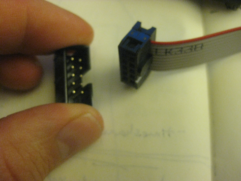
And here's what such a cable looks like in comparison to the size of a raspberry pi:
Using this peripheral approach is nice and modular, and allows us to have several designs share some core code and wiring topology. The downsides that I see are a) increased production costs due to have multiple printed circuit boards, and b) narrowing the design to this particular "port" interface that I sort of just made up (with a lot of input from others, to be sure). Anyway, it's an option, and maybe it'll provide us with a point of discussion for subsequent designs.
A sketchy (unfinished) version of a peripheral that has a light sensor, a motor controller (using a chip suggested by Mat), and a battery controller, is here:
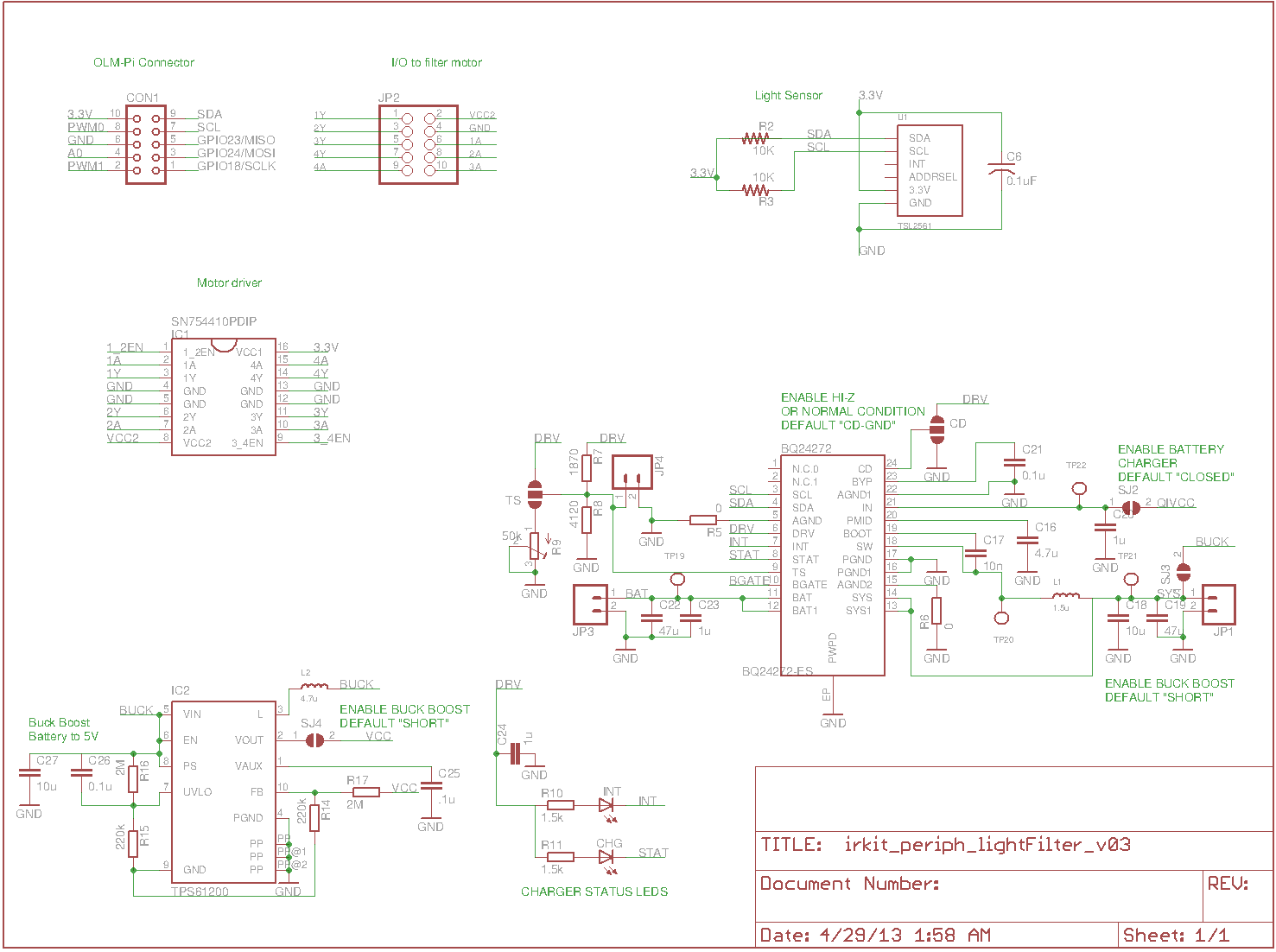
The battery controller part is pretty much just copy-pasted from a really inspiring "Qo Lime Pi" schematic published here. At this point, that part of the schematic is just a placeholder that says "need to learn about batteries" -- I don't yet know the ins and outs of battery control, and that's my next major hurdle in this project.
This design, in which a separate battery controller is located on a peripheral, may be silly. It might be better to have the battery controller located on the main shield, and have power be distributed via the "port" to each peripheral. Maybe I can change my port design to include a "Power" pin (replace one of the digital pins, maybe) ... but then it looks like I might run out of pins on my nice little 2x5 connector.
Hmm. I could simply replace the "3.3V" pin with a "Power" pin; every peripheral could then have additional circuitry to regulate the voltage from whatever "Power" is (5V from the Pi, or even greater voltage from boost circuitry we could include on the shield) down to (or up to) whatever is needed on the peripheral. Would that make better sense?
Anyway, this is a first stab at things. If you like using Eagle, and want to play with the schematics, they're here -- the above files are version "03".
0 Comments
Login to comment.