Materials Used
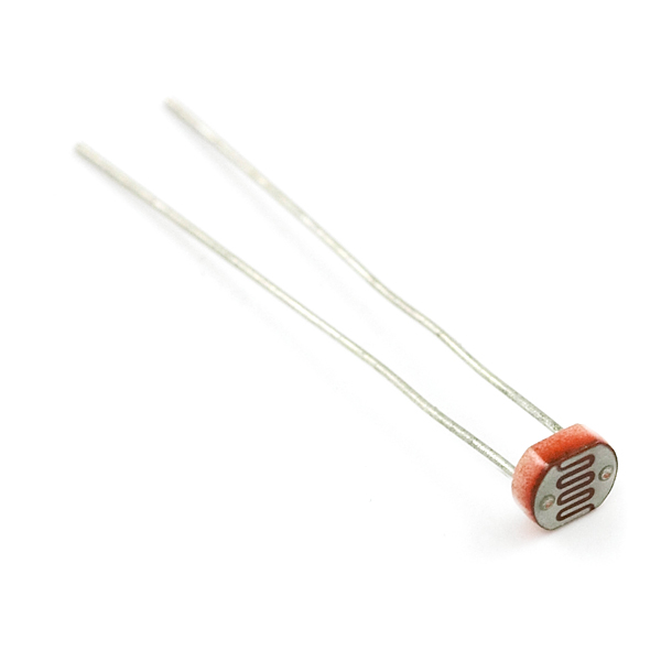
1) Mini Photocell 2) one 10k resistor 3) 3 wires 4) Arduino Uno with breadboard 5) Appropriate filters (see pictures below)
Our very first thought for a filter was to simply color something blue, and use it to cover the sensor. Initially we tried this with clear plastic cups and Sharpies. We quickly realized that this was not a valid option as they still let in a lot of light, and we had no way of determining if light was being filtered. However, this turned out to be a good indicator to test if the sensor is working.

The circular filters are in the 390nm to 430nm wavelegnth bandwidth pass filters, these are an expensive option (picture above). Instead, we found a book of filters for filmmaking and found one filter that fit our range (see below)

Wearable-Version (in addition to above) 5) 2 long wires (approx the length of your shoulder to hip) 6) a "three-way plastic tube" with the bottom tube sawed off 7) soldering materials 8) shrink tubes (various sizes)
Purpose
To measure the amount of blue light we encounter on a daily basis and how smartphones add to that exposure
We are interested in the blue light at 450-470nm

Project Goal
Create a wearable device that filters/detects blue light through use of Arduinos
Setting Up
We used the direct set-up from Rookie Electronica (http://rookieelectronics.com/light-sensor-using-arduino/) in which the user shows how to set up the sensor to the board.
Summary of Rookie Electronics on how to set up sensor (see pictures below): -Connect one pin of the 10k resistor to GND and the other to A0, -Connect to power, -Connect photocell to 5V,


Then we uploaded the code to Arduino and set the delay from 50 to 300. Afterwards, we opened the Serial Monitor to see the data. You should see numbers ranging from 0 to 1023 lux, which is the unit.
Testing the sensor
To test if the sensor is responsive, simply hover your hand above the photocell. You should see numbers drastically dropping with the hand over it and the numbers go back up once the hand is removed. Your sensor is working.
"Light-proofing" the photocell
PHASE 1: The Box We used a box to house the sensor and created a hole and attached a tube. The photocell will be directly under this in order to measure controlled light as much as possible.


Then we also wanted to mimic the distance from the sensor to the light from a smartphone by placing another box on top, which is approximately 14" tall. A small cut out was made at the bottom to accommodate the tube/sensor from the earlier box. (Interesting fact: our "first" box was a pizza-sized box).


Once the boxes were set up we began to record data. We wanted to test how different light sources and filters combined created a range of lux.
PHASE 2: The Wearable To convert the box into a wearable we needed connect the 2 wires to the photocell. First we stripped the ends of the wires so the wiring was shown. Then, we twisted the wiring and soldered the ends so that the wiring did not break apart of each of the four ends (Note: we did not connect them).
We also has a "three way" plastic tube (shown as an example picture here, do not worry about the the set up in the picture), it is shaped like a "T" but we sawed off the bottom opening to now look like an "L". We put the wiring through the L-tube.

Now, we cut the 2 shrink tubes to size (about ~1inch each) and placed it through each wire (1 per wire). Then we inserted a larger shrink tube that enveloped both wires.
Afterward, we wrapped one "leg" of the photocell on the end of one wire and repeated this for the other leg on the second wire. Finally, we soldered the two connections so the photocell was attached to the two wires.

We then applied heat to the shrink tubes so that the connections were finalized and nothing moved (first the smaller shrink tubes (picture below), then once that shrunk, the bigger tube was moved over the shrunken tubes to envelope the two wires together.

Once the tubes have cooled from the heat, pull them through the L-Shaped plastic tube so that look like this picture below. You can see the sensor from the photocell peeking out.

Connect the ends of the two wires to the Arduino board.
Determining the right range of blue light
We chose to focus on filtering blue light at the 450-470nm range, the wavelength most commonly found in smartphones

Finding the right filter
You can look online for filters with specific wavelengths. Once you do, you can glue it to the wearable like this


Results
We found blue light in the 450-470nm wavelength in most of our light sources (fluorescent indoor, smartphones) and we also concluded that the distance from light source affects results.
Issues and Improvements
Filters were not a specific wavelength (more expensive), we previous used conductive tubing in our Phase 1: Box set up which affected our results (be careful!). We also found that the plastic tube in our wearable that houses the photocell lets in light, so a black L-shaped tube would be preferable.
Room for improvements include a better measurement than lux, lux only measures brightness so it does not tell you what wavelengths you are detecting. Although our filter for the 450-470nm range was accurate, it still detected wavelengths from 700+ but at smaller levels. This obviously would affect our data. Finding a more specific filter that only targets 450-470nm only would be good for the future.
Another room for improvement would be making detachable filters for the wearable. Once the sensor was in the L-shaped tube, we just glued the filter over the tube opening, permanently sticking the filter on the wearable.
We were also not successful in using the real time clock and implementing a data logger due to time constraints.

Another way to improve would be to make this sensor even smaller with Arduino Zero for example.
Conclusion
Sometimes people don't realize how much blue light they are exposed to and by making a sensor wearable, they can determine if they get high levels of blue light exposure over the course the day and night (indoor lighting!). Using real time clock, they can determine where they were at a given time based on the data shown and perhaps where they experience the highest levels or the longest exposure. This can help them determine any lifestyle changes they might need to implement.
0 Comments
Login to comment.