Assemble the Thermal Flashlight
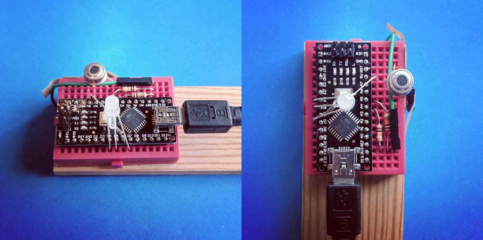
Assembly is a bit easier in this new version (April 2019); below is the diagram both on and off of a mini breadboard; we've eliminated some unnecessary parts.
Parts list:
- 1 Melexis MLX90614 non-contact IR thermometer (3v)
- 1 RGB common-cathode LED
- 2 4.7k Ohm resistors (or close to that)
- a short wire (to extend one leg of the thermometer)
- a mini breadboard
- an Arduino Nano
- a mini USB cable to power it (and a USB battery)
(step-by-step coming soon!)

Program the Arduino
If it's not already programmed, you'll need to upload a program to your Arduino in the Arduino IDE (https://arduino.cc or the online editor at https://create.arduino.cc) using the following code:
https://gist.github.com/jywarren/1ad7dd997b6319ccb2525958709125ab
You'll need to install the Adafruit Melexis library here:

Using the Thermal Flashlight
You can use this program to "paint" colored light with your Thermal Flashlight:
- http://glowdoodle.com
- Also try (and modify) this version in p5js: https://editor.p5js.org/jywarren/full/dl7B2Upp-
See examples of use below!
All code and Fritzing files available here: https://github.com/publiclab/thermal-flashlight/
Old documentation:
https://gist.github.com/sdosemagen/1739961#file-thermalflashlight-ino
Based on a redrawn diagram of the thermal flashlight posted by @ad: http://publiclaboratory.org/notes/ad/11-28-2011/thermal-camera-arduino-uno-mlx90614-ir-thermometer
13 Comments
Illustration made in Fritzing (fritzing.org).
Reply to this comment...
Log in to comment
I've tweaked the code on the thermal flashlight a bit. In our testing, we were getting red for hot, but blue-green for cold (and figured 'blue' should be for the cold).
Here is a reference on how the color HSV (hue, saturation and value) converts to RGB:
http://en.wikipedia.org/wiki/HSV_color_space
Figure 24 shows the essence of what we are trying to do; 0 degrees = red; 240 degrees = blue.
The code in the sketch is almost correct; originally, the value was 360*0.6 = 216 degrees for the coldest value, which is blue-green. 240 degrees gives you blue, so you have:
// Regular ol' RGB LED: // original //int hue = map(state,0,255,(360.00*0.60),0); // not the whole color wheel // // 0 degrees is red, 240 degrees is blue // See http://en.wikipedia.org/wiki/HSV_color_space // Figure 24. // 0=cold is 240 degrees (blue) // 255=hot is 0 degrees (red) int hue = map(state,0,255,240,0);
setLedColorHSV(hue,1,1); //We are using Saturation and Value constant at 1
The other part of the code that will have to change is that if you use a common anode RGB LED (the LED from RadioShack is 276-0028 (common anode (+), which is at 5V), when the PWM output is at 255 for a particular color (5V is on all the time), that color in the LED will be off. So we have to invert the output (zero becomes 255, 255 becomes zero):
// Since we are using common anode, when value is 255 (on always) // the LED for that element is OFF, so, make a swap setLedColor(255-red,255-green,255-blue);
Reply to this comment...
Log in to comment
Thank you very much for this circuit.
Reply to this comment...
Log in to comment
Has anyone built this circuit with the BlinkM MaxM? If so, could you please explain how you connect it to the Arduino? On the diagram above I see the PWM pins are used for the led, but since the BlinkM MaxM got built in PWM I guess this won't work? Is it possible to just disconnect the Master board and use the Blaster led cluster alone, connected to the PWM pins on the Arduino like in the diagram? :O
Is this a question? Click here to post it to the Questions page.
Reply to this comment...
Log in to comment
I've been trying to figure out the MaxM here: http://publiclaboratory.org/notes/warren/12-8-2011/rgb-color-knob-small-steps-towards-thermal-flashlight
not a lot of progress just yet. Kyle from NYC managed it, but I haven't been able to unravel his code yet.
Reply to this comment...
Log in to comment
I have just built a test unit of this, seems to be working well.
For the moment I have the colouring scaled from pink, through blue, cyan, green, yellow, orange, red and finally purple. Currently have all of that set using intervals of the temperature (10-30oC), but might see if I can get that into an equation format (may be a sinusoidal one?) to make it a bit more flexible and configurable. Saw something that someone has already written somewhere to do this, so going to check that out.
I plan to add two switches on it, one that will change the lowest temperature and a second that changes the total temperature range. That should make it a bit more flexible for use.
Got rid of all that silly oF from the program too ;-), now just in oC, makes much more sense :-)
Is this a question? Click here to post it to the Questions page.
Reply to this comment...
Log in to comment
Hmm, may be yours above does something similar already?
Don't really understand the code, not my strong point, will have to have a play and see ....
Is this a question? Click here to post it to the Questions page.
Reply to this comment...
Log in to comment
Now have my program fully working, seems to do what I want it to do.
Issue now is the fact that the 3 colour LED doesn't mix fully, if you have all three on then you have distinct spots of red, blue and green. Looking around now for a lens that will mix them correctly, so that get the actual colour over the entire area, rather than just where the three colours happen to mix.
Reply to this comment...
Log in to comment
Jeff, not sure how to reply to your message, where is the message / contact panel here?
Anyway, I will definitely putting it up here to share with others.
At the moment it is mostly just the coding. I have worked out the formula to do the colour mapping for the range purple to pink (did that in Excel), just have to get that into the programming language so that it works. Basically it is the colour wheel, from 300o for the coldest, then as the temperature increases it goes around the wheel of decreasing angle, through zero and to 330o for the hottest temperature. Working off the following image http://basecase.org/2011/12/hsv
Is this a question? Click here to post it to the Questions page.
Reply to this comment...
Log in to comment
just awesome... but i'm little confused, how many LED you used?
-Shuvojit Das
Is this a question? Click here to post it to the Questions page.
Reply to this comment...
Log in to comment
Sorry folks, i hadn't been getting email updates for these comments; I will now though!
I'm trying to adapt the Visualight to do this, much smaller: http://publiclab.org/notes/warren/11-15-2013/visualight-board-for-thermal-flashlights
Reply to this comment...
Log in to comment
Greetings from Barn Raising 2014. Live from Lumcon! We just finished a wonderful workshop on this tool, and there was a bit of a kerfuffle (slightly over dramatic) surrounding the file downloads. The links on this page to download files from buldr are not working for me (they work for others). We've created a folder that has all of the files in one place on the wiki page: http://publiclab.org/wiki/thermal-camera. I think it would be worth putting a link at the top of this page to the wiki which can be the place for the most up to date files/links etc.
Reply to this comment...
Log in to comment
Quick update based on
https://gist.github.com/jywarren/1ad7dd997b6319ccb2525958709125ab
Using this library! https://learn.adafruit.com/using-melexis-mlx90614-non-contact-sensors/wiring-and-test
Reply to this comment...
Log in to comment
Login to comment.